
Tekla Structures and RISA-3D/RISAConnection have different nomenclatures for how elements are named. To map these names between the two programs a mapping file is generated by the RISA-Tekla Link for each Tekla Structures environment:

This mapping file contains materials, section names, etc., and maps Tekla Structures nomenclature to RISA-3D/RISAConnection and vice-versa. The mapping files are based on the default information in the Tekla Structures environments and the RISA-3D/RISAConnection shape databases. If new sections are added to these databases then they will ALSO need to be added to the mapping file for the RISA-Tekla Link to map these properties between programs.
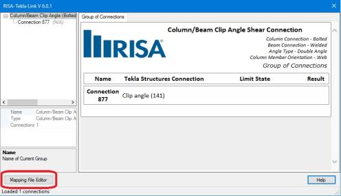
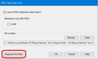
There is no problem opening the .xml mapping files in a spreadsheet program and making edits. However, the format of this file is somewhat difficult to understand. In lieu of this option there is a Mapping File Editor button, accessible a few different ways.
|
| RISAConnection-Tekla Link Dialog |
|
| RISA-3D Tekla Link Export/Import Dialogs |
When this button is pressed the Mapping File Editor will open. When it opens the program will read the shape, material and bolt information from the environment you are currently working in. It will also read from the associated RISA shape database. Finally, it will read and populate the dialog with information from the given mapping file.
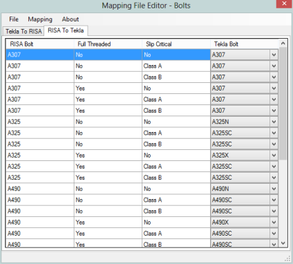
Note that in the Mapping drop-down list is where the option for profiles (shape), materials or bolts is located.
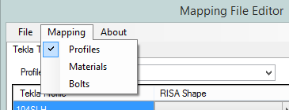
Each item (profiles, materials, bolts) has a separate view with both "Tekla to RISA" and "RISA to Tekla" tabs. When a change is made to mapping behavior this change will automatically occur on both tabs.
Note:
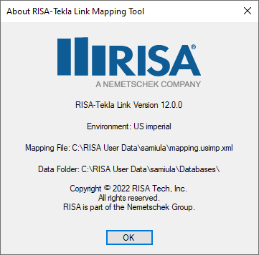
The About dialog will tell you which environment is being used, the mapping file URL and where the editor is looking for the RISA shapes database.
Note:
Member shapes are mapped between Tekla Structures and RISA by way of a mapping file. There is a default mapping file added at install time that has standard shapes mapped. To edit the mapping file you can open in directly. An easier way to edit, however, is via the Mapping File Editor.
Note:
Materials are automatically mapped between Tekla Structures and RISAConnection for wide flanges, tubes, pipes, angles and plates. Tekla Structures has many materials not supported in RISAConnection. If RISAConnection does not support that material a warning will be given and a default material will be used.
Note:
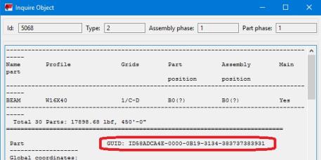
The link uses two connection identifiers when referring to a specific connection with the link. The connection GUID is what the link maps to. This is a unique value for each connection. This value is a very long string, however, so the link uses the CONNECTION_RUNNING_NUMBER as the displayed name of the connection.
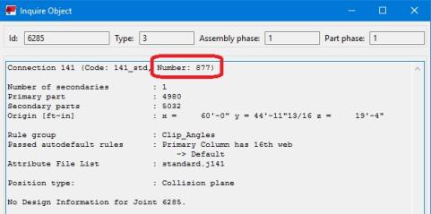
However, you can update this using the  button in Tekla Structures. See the Application Interface topic for more information on this.
The link uses the object GUID when referencing an element.
When transferring Tekla Structures connections to RISAConnection properties are mapped over from Tekla Structures to RISAConnection and vice-versa. Tekla Structures and RISAConnection are very different and were built for different applications. However, many properties can be mapped directly between the two programs.
Properties are characterized as one of three different classifications: read-only properties, editable properties and ignored properties. Here we will explore each classification.
Read-only properties are properties brought in from Tekla Structures that can not be updated in RISAConnection. These are properties inherent to the structure itself. These include section properties, material properties and loading. These are items that in most cases the connection designer does not have control of. Thus, these properties must be edited in the Tekla Structures model and is read-only in RISAConnection. There are also some other properties that for mapping purposes are brought over as read-only as well.
In RISAConnection you can have multiple configurations that Tekla Structures does not support. Because of this it is required to set the bolt hole types in Tekla Structures only.
For more information see the Bolt Hole Mapping section.
Editable properties are properties brought in from Tekla Structures that can be updated in RISAConnection. These are properties specific to connection design that the connection designer would have control over. This includes welds, bolt criteria, plate and clip angle criteria, offsets, etc. These properties, if updated in RISAConnection, will be updated in the Tekla Structures model when the results are exported back from RISAConnection.
Ignored properties are properties completely ignored by the RISA-Tekla Link. These are generally elements in Tekla Structures that are not supported in RISAConnection. Some examples of properties ignored by the link:
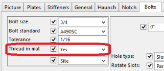
Tekla Structures has the ability to define/edit properties in a variety of ways. The RISA-Tekla Link maps properties between Tekla Structures and RISAConnection in the following priority order:
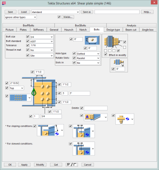
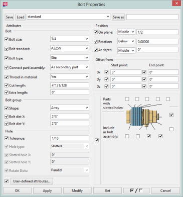
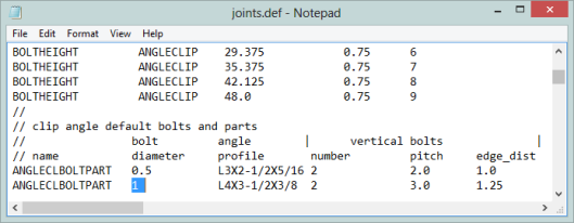
Tekla Structures uses the joints.def in specific folder sequences. The order that it looks in is:
Below is a table showing the possible values that could be used directly from the joints.def file.
| Component 141 | Component 144 | Component 146 | Component 134 | Component 182 |
|---|---|---|---|---|
| Beam bolt vert edge dist | Bolt vert edge dist | Plate thickness | Bolt vert edge dist | Plate thickness |
| Beam bolt horz edge dist | Bolt horz edge dist | Bolt vert edge dist | Bolt horz edge dist | Bolt vert edge dist |
| Column/girder vert edge dist | Rows of bolts | Bolt horz edge dist | Rows of bolts | Bolt horz edge dist |
| Column/girder horz edge dist | Row spacing | Rows of bolts | Row spacing | Rows of bolts |
| Rows of bolts | Columns of bolts | Row spacing | Columns of bolts | Row spacing |
| Row spacing | Column spacing | Columns of bolts | Column spacing | Columns of bolts |
| Columns of bolts | Cope width | Column spacing | Column spacing | |
| Column spacing | Cope length | Cope width | ||
| Cope width | Cope length | |||
| Cope length |
| Components 58, 59 and 60 | Components, 11, 20, and 62 | Component 184 |
|---|---|---|
| Col/Gusset, Beam/Gusset, and Brace/Gusset bolt vert edge dist | Brace/Gusset bolt vert edge dist | Plate thickness |
| Col/Gusset, Beam/Gusset, and Brace/Gusset horz edge dist | Brace/Gusset horz edge dist | Bolt vert edge dist |
| Col/Gusset, Beam/Gusset, and Brace/Gusset Rows of bolts | Brace/Gusset Rows of bolts | Bolt horz edge dist |
| Col/Gusset, Beam/Gusset, and Brace/Gusset Row spacing | Brace/Gusset Row spacing | Rows of bolts |
| Col/Gusset, Beam/Gusset, and Brace/Gusset Columns of bolts | Brace/Gusset Columns of bolts | Row spacing |
| Col/Gusset, Beam/Gusset, and Brace/Gusset Column spacing | Brace/Gusset Column spacing | Columns of bolts |
| Gusset Dimensions | Gusset Dimensions | Column spacing |
| Diagonal Brace Dimensions | Diagonal Brace Dimensions | Cope width |
| Cope length |
Slip-critical nomenclature is not identical between both programs. Here is how the mapping is defined in both directions for the US Imperial environment. The best way to see this information for other environments is from the Mapping File Editor.
| Tekla to RISA Translation | RISA to Tekla Translation | |||||
|---|---|---|---|---|---|---|
| Tekla Bolts | RISA Bolts | RISA Bolts | Tekla Bolts | |||
| Bolt Standard | Bolt Material | Slip Critical | Bolt Material | Slip Critical | Bolt Standard | |
| A307 | A307-N | No | A307-N | No | A307 | |
| A325M | A325M | No | A307-N | Class A | A307 | |
| A325MT | A325M | No | A307-N | Class B | A307 | |
| A325N | A325-N | No | A307-X | No | A307 | |
| A325N-DTI | A325-N | No | A307-X | Class A | A307 | |
| A325_TC | A325-N | No | A307-X | Class B | A307 | |
| A325_TC-DTI | A325-N | No | A325-N | No | A325N | |
| A325N_TC-DTI | A325-N | No | A325-N | Class A | A325SC | |
| A325SC | A325-N | Class A | A325-N | Class B | A325SC | |
| A325SC_TC | A325-N | Class A | A325-X | No | A325X | |
| A325T | A325-N | No | A325-X | Class A | A325SC | |
| A325X | A325-X | No | A325-X | Class B | A325SC | |
| A325X-DTI | A325-X | No | A490-N | No | A490N | |
| A325X_TC | A325-X | No | A490-N | Class A | A490SC | |
| A325X_TC-DTI | A325-X | No | A490-N | Class B | A490SC | |
| A490M | A490M | No | A490-X | No | A490X | |
| A490N | A490-N | No | A490-X | Class A | A490SC | |
| A490N-DTI | A490-N | No | A490-X | Class B | A490SC | |
| A490N_TC | A490-N | No | A325M | No | A325M | |
| A490N_TC-DTI | A490-N | No | A325M | Class A | A325M | |
| A490SC | A490-N | Class A | A325M | Class B | A325M | |
| A490 SC_TC | A490-N | Class A | A325M | No | A325M | |
| A490X | A490-X | No | A325M | Class A | A325M | |
| A490X-DTI | A490-X | No | A325M | Class B | A325M | |
| A490X_TC | A490-X | No | A490M | No | A490M | |
| A490X_TC-DTI | A490-X | No | A490M | Class A | A490M | |
| A490M | Class B | A490M | ||||
| A490M | No | A490M | ||||
| A490M | Class A | A490M | ||||
| A490M | Class B | A490M | ||||
Note:
In the Tekla Structures components there is a button for welds:

This is the place where the Weld Size and Weld Type is stored.
A couple of notes on this dialog:
In Tekla Structures the Electrode Classification is almost never stored in the component. You must click on the individual weld object to view this information. The table shows how this information is mapped.
| Tekla Electrode Classification | RISA Electrode Type |
|---|---|
| 35 | Unsupported (use E70) |
| 42 | Unsupported (use E70) |
| 50 | Unsupported (use E70) |
| E60XX | E60 |
| E70XX | E70 |
| E80XX | E80 |
| E90XX | E90 |
| E70XX* | E100 |
| E70XX* | E110 |
Note:
In RISAConnection you can have multiple configurations that Tekla Structures does not support. Because of this it is required to set the bolt hole types in Tekla Structures only.
In Tekla it is possible to map the type of bolt holes to RISAConnection.
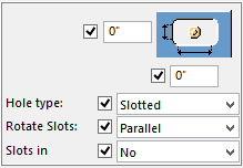
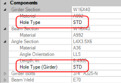
This is the nomenclature that is used:
| Tekla Hole Type | Tekla Rotate Slots | RISA |
|---|---|---|
| Default | Odd | SSLH |
| Default | Even | SSLV |
| Default | Parallel | SSLH |
| Default | Default | STD |
| Slotted | Odd | LSLH |
| Slotted | Even | LSLV |
| Slotted | Parallel | LSLH |
| Slotted | Default | LSLH |
| Oversized | Any Value | OVS |
If the hole dimensions are defined explicitly an warning will be generated and RISAConnection will default to a STD hole. RISAConnection bases the standard hole size (STD) and slotted hole sizes on values taken directly from the AISC steel manual. Again, if you input dimensions directly they will not be used.
Note: